chinese carburetor

Arborist Forum

Help Support Arborist Forum:

This site may earn a commission from merchant affiliate links, including eBay, Amazon, and others.
I got into a private discussion with a member of the forum about the flow through the venturi. I thought I might take the salient points and put them into this thread for the rest of you guys to peruse. I've also edited the discussion to try and make the points a bit clearer.
-------------------------

XXX, think about an airplane's wing and the shape of the airfoil. The reason the airfoil makes lift is that the air going across the top of the airfoil has to travel a longer distance than the air under the wing. The air has to go faster over the top of the wing, that creates a lower pressure.
The venturi in a carb has the cross-section of an airfoil. The air closest to the surface of the venturi is going faster than the air in the middle of the venturi. Take a look at the flow diagrams of the air flow in a venturi and you will see what I mean.
As the flow through the carb increases, the low pressure area along the surface of the venturi increases and begins to extend further away from the edge of the venturi.
What that means is that if you put the opening of the nozzle on the surface of the venturi it will respond quicker to an increase in flow through the carb. If you put the opening of the nozzle in the middle of the venturi, the low pressure isn't as great and the low pressure on the nozzle tip isn't as great. It takes a while (increasing the revs/flow) before the nozzle detects the same low pressure as the other nozzle on the surface of the venturi.
The nozzle closest to the surface of the venturi will respond sooner and tend to fatten up the mixture at lower revs/flow.
 
However, just as an initial observation it appears that XXXXX statement is internally inconsistent. He states that the mass in the venturi travels at the same speed, then he states that they place the nozzles up in the venturi for better atomisation. OK, the only thing that would promote better atomisation would be an increase in speed which would produce greater shear forces on the tip of the nozzle - so, which is it, same speed through the venturi or increased speed towards the center?
If he is implying that placing the nozzle tip closer to the center gives a more uniform fuel mixture, then I will disagree. This is a two-stroke that has a thrashing machine under the piston (the crank and rod) to stir up the mixture. Further, I've worked on stratos where there is considerable difference between the pure air coming out of the transfer ports followed by the mixture. No matter what variations of timing (say 10 degree extra strato compared to intake) the resultant mixture at the time of combustion appears to be homogenous. I expect that most of this may be related to the vaporisation of the fuel as it enters the cylinder where the majority of vaporisation occurs. I was surprised by reading Blair's work how much of the vaporisation does occur in the cylinder, after which I understood why a water-cooled two-stroke makes better power than the air-cooled two-stroke.
I also disagree with his ramming effect comment. I'll pull up some diagrams of flow through venturis to explain my thoughts.
As far as atomisation, I'd be interested in any information that XXXXX has on the nozzle tips. There is a considerable variation in various tips. Some have larger diameter openings than others. I think it may effect the amplitude of the 'signal' on the high speed circuit, but I don't know. There is also the tips with multiple openings and an increase in the 'edges' that would promote better atomisation as the fuel is pulled away from the edges.
He might also have information on why there are so many different lengths of nozzles. I understand that a smaller venturi would need a longer nozzle to get clear of the edge of the venturi, but it is the large difference in lengths I see in the venturi that interest me.
 
There was some discussion about possible 'ram' effects of the increase in velocity through the venturi, this is my response.
-------------------

Here's some more on the venturi - https://en.wikipedia.org/wiki/Venturi_effect

First the ram effect. Notice that the velocity through the venturi drops when it exits the venturi. There is no ram effect felt at the intake.

The ram effect 'could' be utilised if there was enough intake timing to justify the ram effect to push against the backflow from the intake. However, even with 160 degrees of intake duration there isn't any backflow even when the saw bogs. Putting a long enough intake to set up a freight train of mixture towards the saw would be the biggest problem. I have done resonance tuning of two-stroke intakes and THAT does work. The easiest way would be to put a hose off of the intake between the carb and cylinder. You could trim the length of the hose to get the intake tract volume you wanted, then shift the hose inside the handle of the saw. Gotta try that one day.
 
Here's a bit more on the pressure gradients in the venturi.
-----------------------------------------------

Here's one on the pressure gradients over the top of an airfoil. See figure 3.7

http://www.av8n.com/how/htm/airfoils.html

They change the pressure gradients in the pictures by changing the angle of attack, but the same principle applies with the velocity of air flow. Notice how the negative pressure is greater closer to the top of the wing. The same thing applies in the venturi, the pressure drop will be greater closer to the surface of the venturi.

Here's something I ran into while researching these diaphragm carbs - the guys flying with the ultra lites were modding the carbs with a longer discharge nozzle. They wanted to lean out the mixture when they were at 'cruise', in other words, when they closed the throttle for less power. I figured what was happening was with the throttle valve partly closed it created a strong low pressure area behind the throttle plate which was pulling extra fuel from the low speed circuit. They put in the longer nozzles which became less effective when the total airflow through the venturi was reduced, or to put it another way, when the pressure gradient at the nozzle tip was reduced. The result was less fuel from the main circuit to compensate for the extra fuel from the low speed circuit.
 
Last edited:
There was a discussion on boundary layers and the possible effect through the venturi.
-----------------------------------

Here's one on boundary layers in a venturi - http://www.efm.leeds.ac.uk/CIVE/CIVE1400/Section4/boundary_layer.htm

If you go to the end of Sec. 2 you will see they refer to the boundary layer being very thin - just a few hundredths of a mm.

Then in Sec. 5 they discuss the boundary layer going into a convergent cone (entering the venturi), in which case the boundary layer decreases, they say the boundary layer actually does not occur in a convergent cone.
 
I've been fighting a 272xp that will tune when it's out of wood and die in the cut, as it turns out, the high speed needle is loose in the threads and sucking air. I ordered the over seas carb and will give it a try. Finally figured it out by putting pipe teflon on the needle and the saw cut great.


Try a small o ring and a thin washer behind the spring on the needle.
 
I was just looking at some small carbs today. I noticed that the Walbro WTs have two transfer outlets placed fairly close together, while the ZAMA C1Qs had a single transfer outlet plus an additional outlet placed farther away (on the slope of the venturi, closer to the main outlet). I have not figured out where this outlet draws fuel from.

I was also looking at a Walbro HDB-6B, which has two outlets up by the main venturi - one is closer to the throttle plate. I don't see this documented anywhere and have not figured out how they are fed yet.
 
Many times the only way you can tell is to pull the welsh plug/s. On the Zamas the center well is often fed by a passage that comes in deep in the well. Even with the welsh plug out of the carb it is hard to see where it enters that center well. The C1M carb passages had me completely stumped until I pulled the welsh plugs.

On the Walbro HD I'm modding, the two air bleed/transition ports are drilled at different angles. When you pull the welsh plug you can see one hole is drilled vertical through the carb body, the other goes up at an angle and comes out on the back of the venturi. I couldn't see the exit hole on the venturi until I pushed a piece of wire through it and saw where it came out.

On the Zama C3M those transition holes are fed fuel by the idle jet. On the Walbro the transition holes are fed fuel by the low speed needle.

I just ordered some carb parts and one of the items was a lot of 10 welsh plugs for the HD. To be able to drill the HD, I have to pull the welsh plug each time I want to try a different size hole.

It sure would be nice if someone was to measure a heap of HDs and make a chart referencing the size holes to the displacement of the engine. It could save a lot of time if someone wanted to mod their carb - just look at the chart and drill the right size holes.
 
A pen light and a dark room will reveal some passages.
Anytime you have a carburetor stripped to the body (welch plugs and screws out)
sit down in a dark room with the penlight and put the light in one side of the bore at a time
and block the opposite side with a finger or palm and look for the light in the holes were
the plugs were.
The other trick for corners when light is too hard to see is a dribble from a syringe
or an aerosol can extension tube and look for where the fluid appears.
The syringe can be easier if the needle is intact and can be inserted into an opening.
Heck, use a dab of coffee or something dark in the syringe
If you need some better contrast.
Just don't use anything lumpy - wouldn't want to plug a passage.

We just need someone to get a job at walbro and get hands on some data sheets
for the transition ports.
Mapping out and trying varoius sizes and patterns of those ports and throttle plate notches
would easily be another 3~6 months of dyno time at Chadihams place.
 
Yup, I was using a pen light, but there is a check valve in the H circuit that blocks everything.

Here is another thing to consider: After looking at the new split flow carbs they are using on strato engines, I looked at a standard carb with the choke and throttle plates in the WOT position. In that mode the two plates almost connect, leaving only a small gap between them - they filled that gap in with a "fin" on the new strato carbs, but even without it the flow is pretty well divided. The main outlet is entirely under the choke plate. So that means fuel is really only flowing through half the bore. That's OK, as half the air flows through each side, and ultimately the outlet mix goes into the case where it gets all mixed up. But still, the actual venturi area is half of what it seems. Some carbs have no choke plate and the situation is different then.

I have not really figured out any reason why that should be a problem, it's just something I found interesting. It would seem that with half the air flow and half the venturi area you need to have the jet flow all of the fuel. If you consider two carbs, one with a choke plate and one without but everything else the same, one will need to flow all the fuel at half the air flow through a venturi half the size.
 
We just need someone to get a job at walbro and get hands on some data sheets
for the transition ports.
Mapping out and trying varoius sizes and patterns of those ports and throttle plate notches
would easily be another 3~6 months of dyno time at Chadihams place.

For the Walbros someone could go through a box of old carburettors and measure them. If they were rebuilding their favourite carb, they could measure the holes and add the information to the chart.

The Zama is a much easier carb to mod. You don't have to worry about cutaways on the throttle plate, the idle circuit is separate and controlled by the idle screw. You don't have to pull a welsh plug to drill the jets, just sit the carb down on the edge of the table and ream them out. It would take about a 1/2 hour to mod (and rebuild) the carb.
 
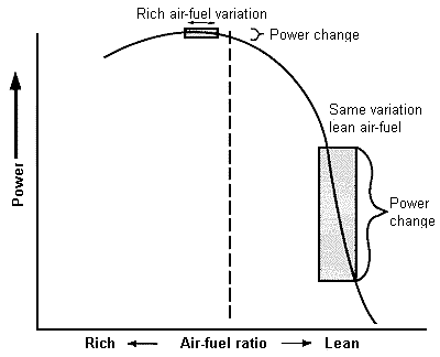
I thought I'd pull this link over from the 7900 carb thread - http://www.mummbrothers.com/SRF_Stuff/Secrets/Driveline/Air_Fuel.htm

I liked this diagram from the article, the EPA likes the mixture in the box on the lean side of the curve, I like the mixture in the box on rich side of the curve -

A_F%20Ratio.gif
 

Latest posts

Back
Top