My Splitter Build (heavy on photos)

Arborist Forum

Help Support Arborist Forum:

This site may earn a commission from merchant affiliate links, including eBay, Amazon, and others.
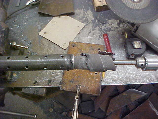
When I was building mine, the guy who sold me the parts and builds them for a living said it is best to use a dispersion tube that is capped off on the end. You can see here what it looks like.

He said this is the best way to insure no swirling of the fluid. I have a single baffle in mine with the dispersion tube on one side and the feed to the pump on the other.

Thanks for the photo, which way did you face the holes?

JT
 
Thanks for the photo, which way did you face the holes?

JT
It is crossed drilled, meaning 4 holes at each location. I tightened it till the holes were on 45 degrees from the bottom so it wasn't shooting straight down.

MVC-019S_38.JPG


If you make one up, be sure to deburr it on the inside to get all the shavings and such out. Either a deburring tool or some wrapped emery and rag on a long rod. I did both as I want no surprises.
 
So what does the diversion tube do? Is that the return? Or am I lost?

The dispersion tube is on the return side after the filter. All it is doing is keeping the fluid from having one solid stream in the tank that would cause a constant, heavy flow in one area. the tube is set down in the tank so fluid doesn't get air borne and introduce air into the system. The end of the tube is capped so the fluid has to go out the small holes. You have to remember, with a 28 GPM pump you are moving a lot of flow all the time when operating. Granted, not at the pressure of the high side but the fluid still has to move. this is how it was explained to me anyway.
 
Even 13 GPM is moving right along to pass through a 3/4" pipe so there is quite a bit of velocity in the oil. Spraying that into the tank is like having your hose nozzle on jet and trying to fill a bucket with some soap in it...

Edit: Seems like a fitting nightmare for me, the cylinder has -12 ORB ports and the only 45° fittings I can find are JIC 37° so that means I can't use Chinlee hoses from the farm supply as they are all NPSM. I can get hoses made at NAPA with JIC 37°. I assume it would be best to just have JIC on both ends of the working hoses?

JT
 
I would disagree with the dispersion tube idea. Every one of those holes is a point where air can be mixed in with the hydraulic fluid and will actually make things worse. The proper way to do it is to have a large diameter (4+") vertical tube inside the hydraulic tank, and have the fluid go in to that at a tangent so it swirls around the inside wall, thereby giving up any air that is entrapped. Holes at the bottom of the tube let the fluid flow out into the rest of the tank.

This is how dry sump oil system tanks are made for race cars that need to remove air from the oil whipped around by the crankshaft that is picked up by the scavenge pump and sent to the oil tank before going back to the high pressure oil pump.

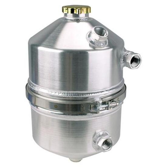
Look at this and notice how the incoming oil fitting on the right comes in off to one side and will shoot the oil on to the inside wall causing it to spin around inside as it falls down. A simple large round tube with an open top and bottom would work fine and accomplish the same thing.

91015120_L.jpg
 
H
I would disagree with the dispersion tube idea. Every one of those holes is a point where air can be mixed in with the hydraulic fluid and will actually make things worse. The proper way to do it is to have a large diameter (4+") vertical tube inside the hydraulic tank, and have the fluid go in to that at a tangent so it swirls around the inside wall, thereby giving up any air that is entrapped. Holes at the bottom of the tube let the fluid flow out into the rest of the tank.

This is how dry sump oil system tanks are made for race cars that need to remove air from the oil whipped around by the crankshaft that is picked up by the scavenge pump and sent to the oil tank before going back to the high pressure oil pump.

Look at this and notice how the incoming oil fitting on the right comes in off to one side and will shoot the oil on to the inside wall causing it to spin around inside as it falls down. A simple large round tube with an open top and bottom would work fine and accomplish the same thing.

91015120_L.jpg
How does air get to the close to the bottom of the tank where the tube comes in with a dispersion tube system? Just trying to learn here. To me, air can only be induced if the fluid squirts/swirls to the top where the air is naturally. The guy who told me, he builds hydraulic stuff for a living, said to make sure it was big enough in length and holes to keep it from having any back pressure. Just wondering out loud here.
 
I purchased a couple of 20gal hyd oil reservoirs that came from Vermeer mfg equipment leftovers and were never used. The return and the 2 suction ports are on the same side (right side when facing reservoir) If you look inside the tank the return line (port is 20SAE in size) makes smooth 90 turn to the left goes across the top of the 2 chambered tank then makes another smooth 90 turn towards the bottom of the tank where it sits 1inch off the bottom. The baffle inside the tank in no more then a piece of plate with a long 1/2in slit at the bottom and small slits on the side to let fluid through. No pipe with small holes or fancy baffles. Probably alot of ways to limit air inducement/entrapment in the oil and mine is an example of one.

Brian
 
I would disagree with the dispersion tube idea. Every one of those holes is a point where air can be mixed in with the hydraulic fluid and will actually make things worse. The proper way to do it is to have a large diameter (4+") vertical tube inside the hydraulic tank, and have the fluid go in to that at a tangent so it swirls around the inside wall, thereby giving up any air that is entrapped. Holes at the bottom of the tube let the fluid flow out into the rest of the tank.

This is how dry sump oil system tanks are made for race cars that need to remove air from the oil whipped around by the crankshaft that is picked up by the scavenge pump and sent to the oil tank before going back to the high pressure oil pump.

Look at this and notice how the incoming oil fitting on the right comes in off to one side and will shoot the oil on to the inside wall causing it to spin around inside as it falls down. A simple large round tube with an open top and bottom would work fine and accomplish the same thing.

I think you're talking apples and oranges here, a racing engine introduces air into the oil at the engine and the device you pictured is to remove that air. In a splitter the object is to not put air into the fluid in the first place and the only place that can happen is in the return line (provided the suction is not sucking air).

my 2 cents
JT
 
I purchased a couple of 20gal hyd oil reservoirs that came from Vermeer mfg equipment leftovers and were never used. The return and the 2 suction ports are on the same side (right side when facing reservoir) If you look inside the tank the return line (port is 20SAE in size) makes smooth 90 turn to the left goes across the top of the 2 chambered tank then makes another smooth 90 turn towards the bottom of the tank where it sits 1inch off the bottom. The baffle inside the tank in no more then a piece of plate with a long 1/2in slit at the bottom and small slits on the side to let fluid through. No pipe with small holes or fancy baffles. Probably alot of ways to limit air inducement/entrapment in the oil and mine is an example of one.

Brian
just because thats how Vermeer does it doesnt mean thats the best or proper way... most tanks are like that though, they just returnt he fluid to the bottom of the tank, but there are better ways. and i definetly wouldnt call Vermeer the best in the business (especially with chippers)...
 
Last edited:
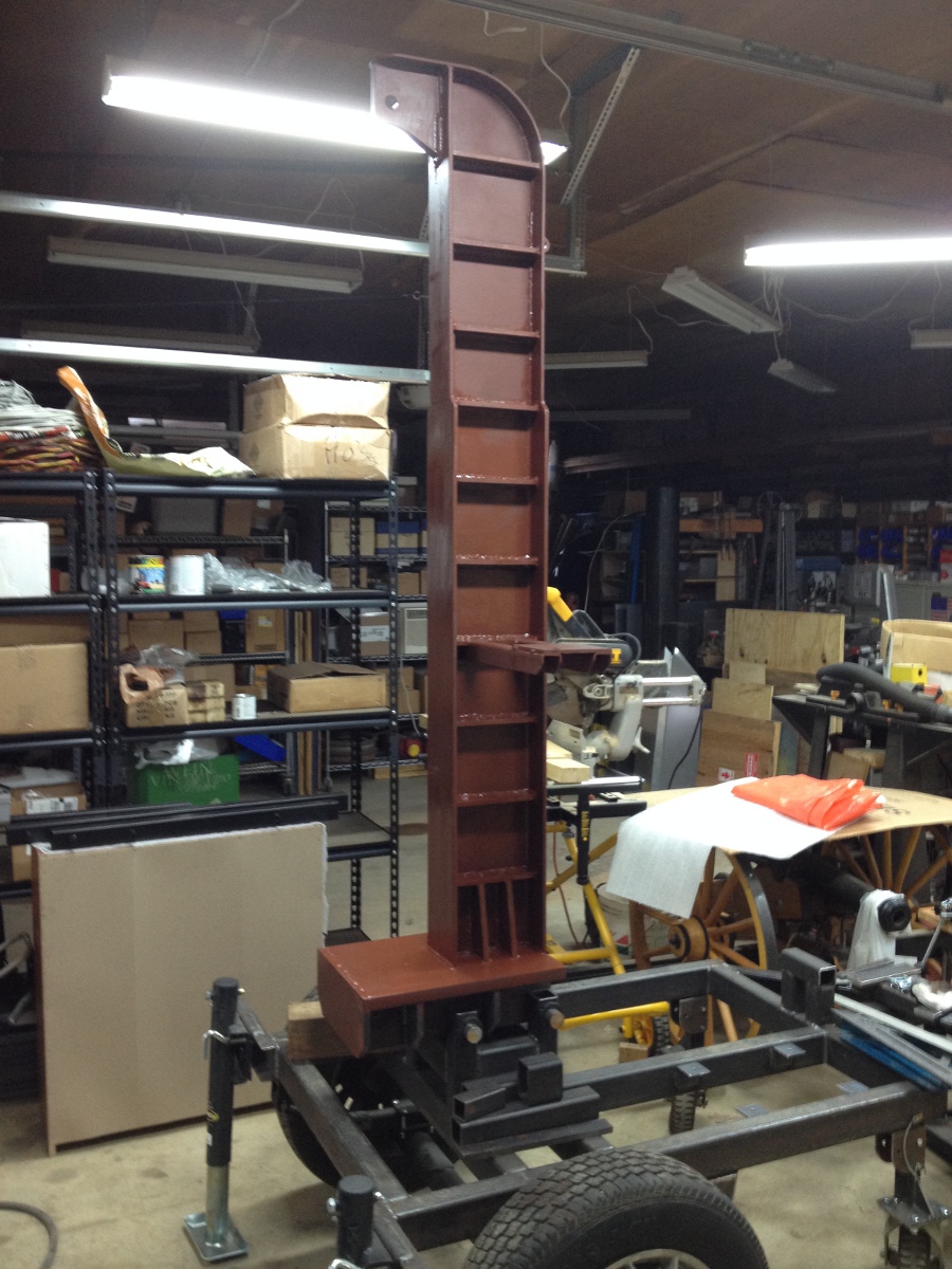
Just to get back on topic, I got the valve mount done and primed the beam. Also you might not see it at first but I removed the cranks from the stabilizer jacks and replaced them with a bolt with the threads cut off. This keeps them from hitting my shin as I move around. I'll use a ratchet or a wrench from the sale barn to raise and lower them.

splitter-17.jpg
 
It's pretty heavy and the splitting cylinder will be the power to raise and lower the beam. I looked into a lift cylinder but by the time I had a long enough stroke cylinder I ran out of room. I even explored some mechanics driven with a short stroke cylinder but that got too complicated. When I want to raise and lower it I'll hook onto the wedge and put a sheave on the reaction plate and connect the other end of the cable to the frame. As I raise the wedge that will pull the beam up into position. Then I just put the pin in.

JT
 
Forget about the splitter, I'll take one of those cannons in the background, please :)

Back to the comments about using the tube with holes in it to remove air from the hydraulic fluid...if said tube is going to be down near the bottom of the tank then I stand corrected. I was visualizing it being up at the top of the tank where the fluid would be effectively sprayed out and then fall down to the fluid level, splashing around, and picking up air.

To be honest, if you don't have a cavitation problem, just plumbing the return to be down at the bottom of the tank should be fine as there shouldn't be any air in the fluid to contend with.
 
I built two of them, one for me and one for a buddy. We now have 4 cannons and 2 mortars.

I think just about any method to return the fluid back to the tank and reduce the velocity without introducing air into the fluid will work. I'm still thinking about how I will do it...

JT
 
0407121400b.jpg I am very interested in this seemingly efficient vertical design with a table. Powersplit International make a couple models with an interesting wedge design that allows two or four-way splitting with the same wedge, and is foot operated. I also am drawn to the SuperSplit at about 40% the price, but at the end of the day it looks like 'tons' of work positioning every re-split and lots of shoulder exercise in the engagement lever over the course of a day (or week). Spinning a vertical round on a table for multiple controlled splits appears easier, and no chasing re-splits as seen in many horizontal demo videos. I do not need a log lift personally, but for those that do, log lifts on most horizontal machines are on the opposite side of the beam as the operator. In the demo videos the operator steps around the end of the splitter making it look simple to load the log lift. The rub for me, as I work alone, is I would have to walk around the far end of the splitter, or around a conveyor. With a vertical table design it is not an issue walking around a beam because the lifts mount to the side of the table. Wish I could fabricate like some of you guys. For now the old SpeeCo is slow but good.
 
My planned log lift is a set of log tongs and a chain and a hook. Lower the wedge all the way down, hook the chain on the wedge and put tongs on round that is too big for me to lift then raise the wedge and lift the round. The only fault with this theory is the cylinder is a 24" stroke and the table is 30" off the ground. Gotta think on that one a while...

JT
 
Most of what I use for hyd work is Parker/Hannford stuff. I will try to get to the pic that I was talking about sorry for taking so long been busy . This is a 1/2 hose to 3/4 oring crimp on fititng elimantes a fitting on the cylinder On the other end of the hose install a female of your choice usaully a JIC although a swivel NPT or a Seal Loc is possiable
 

Attachments

  • S8000324.JPG
    S8000324.JPG
    695.8 KB
Last edited:
Here is apic of the St 90, valve and long sweep suction hose set up On the return side. I am going to use on my tank You get the idea
 

Attachments

  • S8000335.JPG
    S8000335.JPG
    666.3 KB
  • S8000329.JPG
    S8000329.JPG
    1.1 MB
  • S8000304.JPG
    S8000304.JPG
    2 MB
  • S8000305.JPG
    S8000305.JPG
    957.1 KB
  • S8000327.JPG
    S8000327.JPG
    1.3 MB
Lastly a few more hose and fititng pics Last pic kinda hard to make it out its an 3/4 oring to 3/4 npt fitting/adapator to give you a few ideas of how to fit some of the itmes togther without extra bulk or restiction. Any questions ask I will try to answer
 

Attachments

  • S8000301.JPG
    S8000301.JPG
    1.5 MB
  • S8000303.JPG
    S8000303.JPG
    907.4 KB
  • S8000322.JPG
    S8000322.JPG
    607.6 KB

Latest posts

Back
Top