I cut out a piece of 1" steel for my hydro pump to bolt into and welded that to my framework with another brace to hold it in place. Then I set my gas powered engine to that pump using a dial indicator to get it as true as possible while bolting it down-connecting with a love joy coupling. It has worked really well for the last 15 years and it only takes a few minutes to realign if you pull the engine off for some reason.
You are using an out of date browser. It may not display this or other websites correctly.
You should upgrade or use an alternative browser.
You should upgrade or use an alternative browser.
Building a log splitter with a vertical shaft questions
- Thread starter 04Bmals
- Start date

Help Support Arborist Forum:
This site may earn a commission from merchant affiliate
links, including eBay, Amazon, and others.
Wood Hound
ArboristSite Operative
I have a HYD pump on the head of my band sawmill and pump is belt driven-i am able to saw about four hours and it`s time to snug of the pump again,get`s old..
Wood Hound
ArboristSite Operative
Under my C60 is a vertical setup to run the Hiab crane. 18 or 20 hp engine, coupled to an 8 gpm pump. Very little room, marked out the plate to mount the engine to, then made the bracket for the pump. Lovejoy type coupler. I'd recomend bolting it all together, as you can adjust later for the smallest allowances. If you weld it and it's off, well, cut it off & start over. Several years on this setup, a thousand logs or so, gravestones, machinery, etc. I'm in Kent, not far from you in Bristol - If you ever want to take a ride, let me know. Don't laugh at the muffler in pic 2 - that hose clamp is saving me 100.00 - 


04Bmals
New Member
Awesome thank you, that helps out a lot, I may take you up on that if I can’t get it right. I’m going to be grabbing the steel this weekend and get started on it.
Here is how I do it. Just use any pump adapter and make an adapter plate like this:
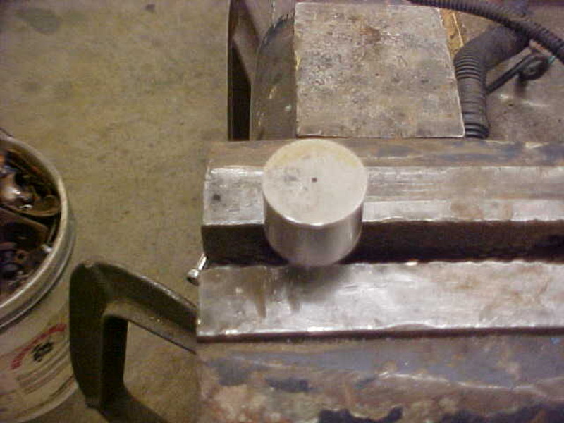
Need to find a diameter that is exactly the same size as the crank and clamp it in the vise.
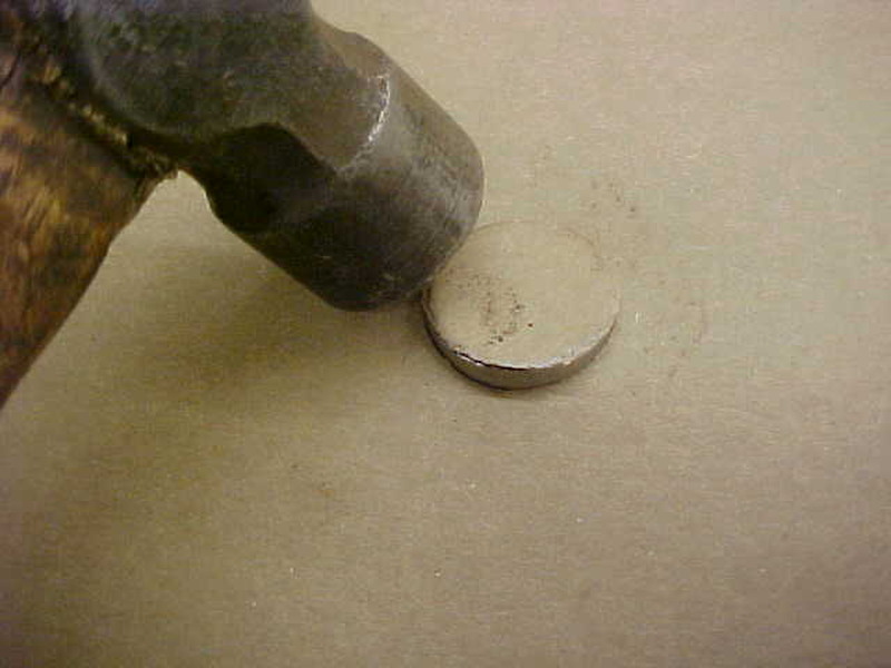
Get some cardboard(like cereal box material) and lightly tap the edges till it is "cut" to size.
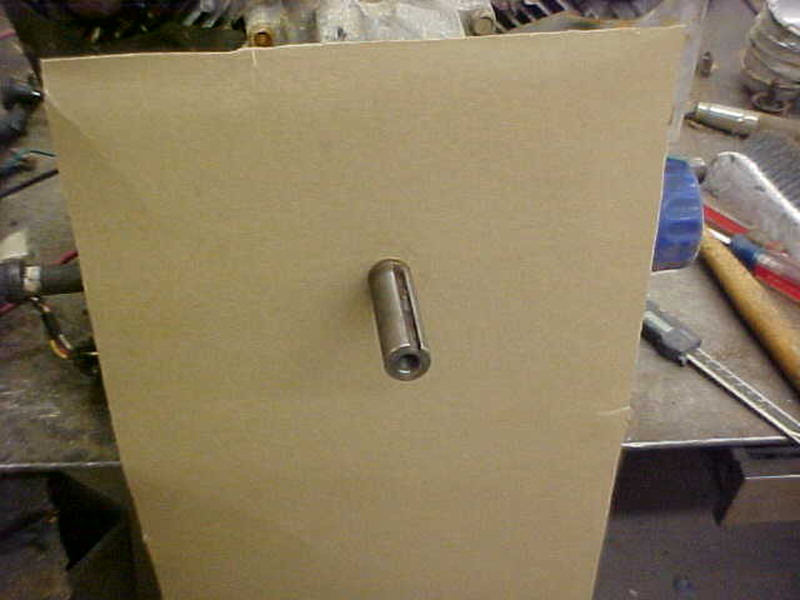
Slip it over the crank.
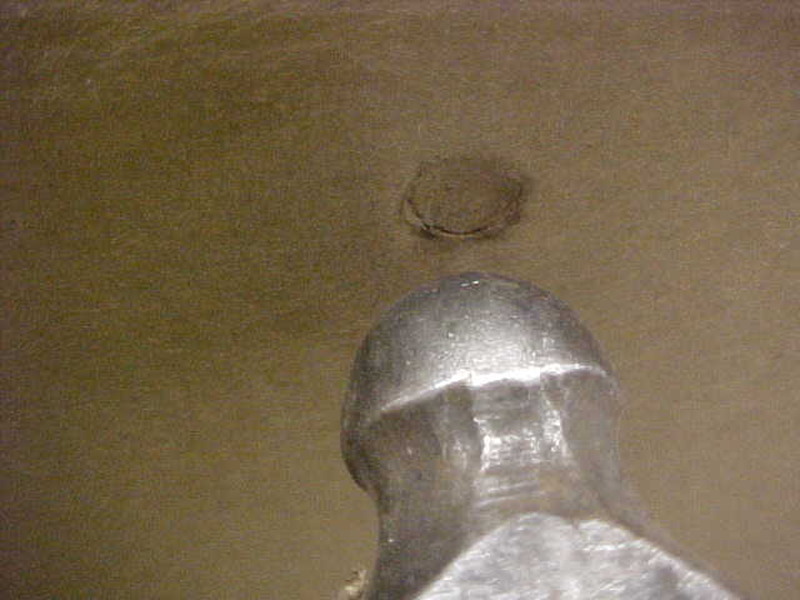
Next, use the other end of the ball peen hammer and tap lightly till it cuts the hole.
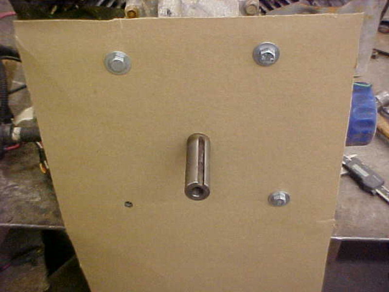
Put a bolt with washer in and snug it up. Move to the next one and repeat till you get them all.
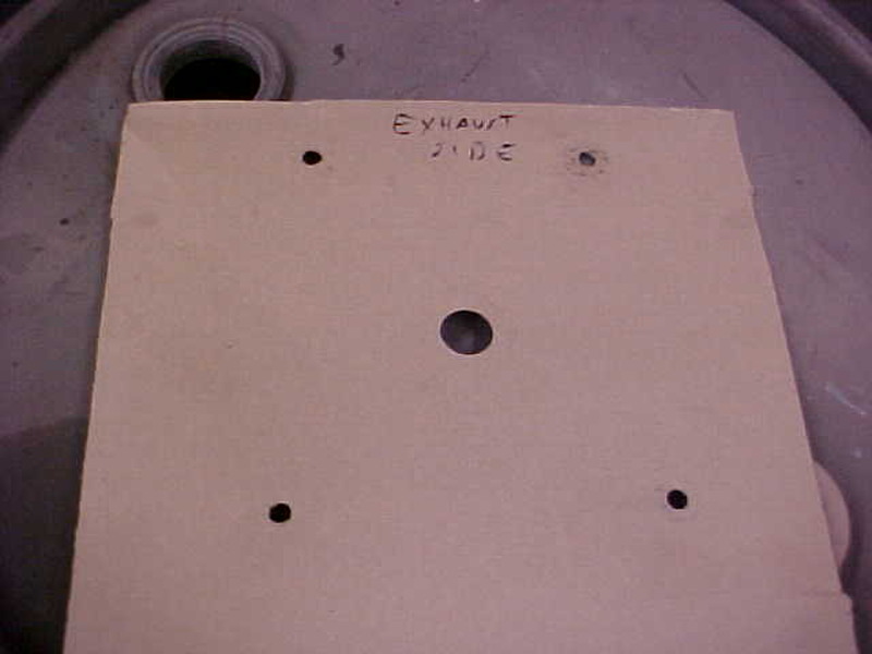
Now you have an exact pattern of the holes and when I measured it's a 10 inch bolt circle. the holes are offset but they are all in the outer edge of a 10 inch circle. this comes into play when you make the hydraulic pump bracket as they have to be true to each other. Notice I give a point of reference (exhaust side) so I don't make a mistake on locations.
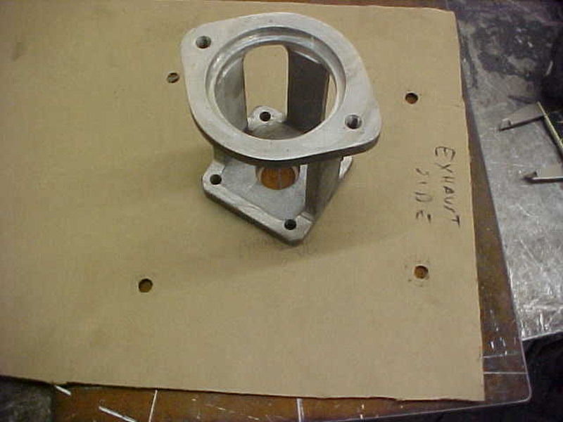
Found the best position to mount the pump for the inlet/outlet ports and used the same method to mark the hole position. Double checked positions measuring out and the bolt circle was even so it is good.
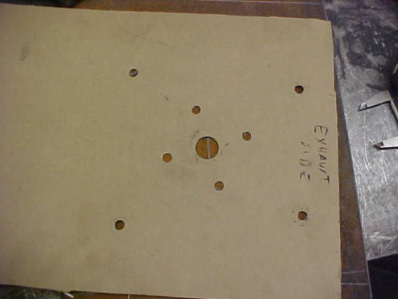
Here is the final pattern ready to transfer to the steel plate. This takes the guesswork out of it and idiot proofs it, which is needed for me!

Need to find a diameter that is exactly the same size as the crank and clamp it in the vise.

Get some cardboard(like cereal box material) and lightly tap the edges till it is "cut" to size.

Slip it over the crank.

Next, use the other end of the ball peen hammer and tap lightly till it cuts the hole.

Put a bolt with washer in and snug it up. Move to the next one and repeat till you get them all.

Now you have an exact pattern of the holes and when I measured it's a 10 inch bolt circle. the holes are offset but they are all in the outer edge of a 10 inch circle. this comes into play when you make the hydraulic pump bracket as they have to be true to each other. Notice I give a point of reference (exhaust side) so I don't make a mistake on locations.

Found the best position to mount the pump for the inlet/outlet ports and used the same method to mark the hole position. Double checked positions measuring out and the bolt circle was even so it is good.

Here is the final pattern ready to transfer to the steel plate. This takes the guesswork out of it and idiot proofs it, which is needed for me!

$79.99
ZELARMAN Chainsaw Chaps 8-layer Protective Apron Wrap Adjustable Chainsaw Pants/Chap for Loggers Forest Workers Class A
QUALITY GARDEN & HAND TOOLS

$194.26
Oregon Yukon Chainsaw Safety Protective Bib & Braces Trousers - Type A Protection, Dark Grey, Large
Express Shipping ⭐⭐⭐⭐⭐

$17.99
$19.99
Extendable Pole Saw Branch Trimmer Pruner Head for Tree Trimming Pruning
FENGLICNSAOMV

$59.99 ($0.40 / Foot)
$69.99 ($0.47 / Foot)
Arborist Rigging Rope Bull Rope Black (1/2 in x 150ft) Polyester Braided Arborist Rope 48 Strands for Tree Work Camping or Swinging…
UIERTIO

$337.83
$369.99
WEN Electric Log Splitter, 6.5-Ton Capacity with Portable Stand (56208)
Amazon.com

$59.99 ($0.40 / Foot)
$69.79 ($0.47 / Foot)
Arborist Rigging Rope 1/2 in x 150 Ft Blue Bull Rope Polyester Braided Arborist Rope 1/2 inch 48 Strands 150 Feet for Various Outdoor Applications Construction Climbing Swing Sailing
Glfcai store

$225.16
OREGON 295397 Type C (All Round Yukon Chainsaw Protective Trouser, Black, Small
Express Shipping ⭐⭐⭐⭐⭐

$37.99 ($0.38 / Foot)
$40.99 ($0.41 / Foot)
Arborist Rope Climbing Rope Swing for Tree(1/2in x 100ft) Logging Rope 48 Strands for Pull, Swing, Knot (Orange)
SDFJKLDI

$19.99 ($3.33 / Count)
Firewood Log Splitter 45mm+32mm + 4 Handles (Square + Round + Hex Shank + Small Hex) Wood Log Splitter Easy Splitter Detachable Drill Bit Heavy Duty Electric Drills Screw Cone Driver Removable
JianShiMoQinDianZiShangWuYouXianGongSi
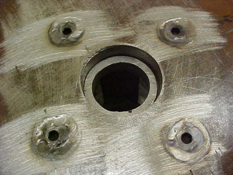
After drilling the holes I recessed the adapter plate holes on the motor side. Normal bolts would hit the bottom of the motor and needed a way to hold them. I used angle head allens and TIG welded them into the countersunk holes
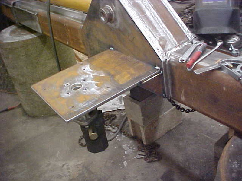
Tack weld and check everything and weld it solid.
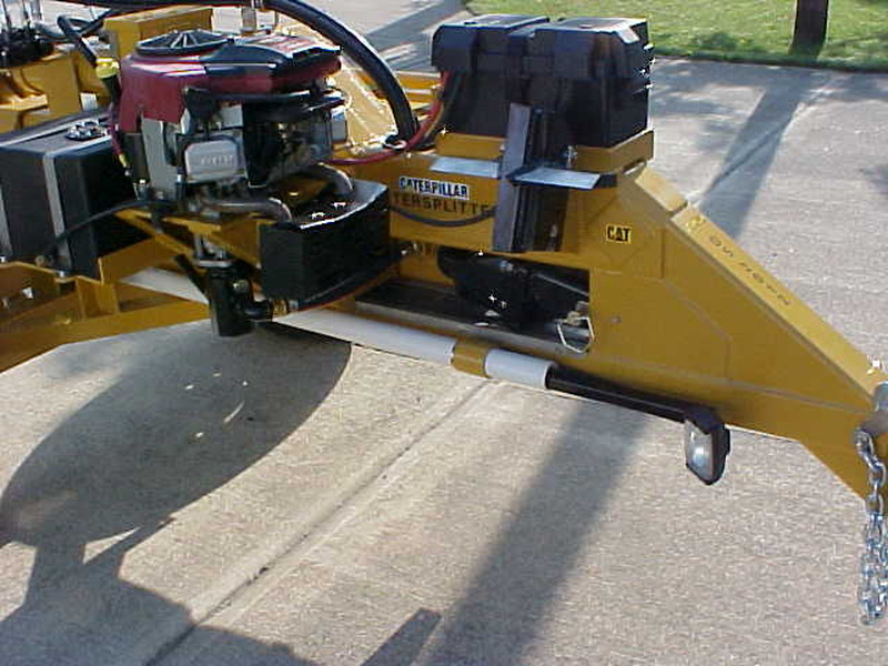
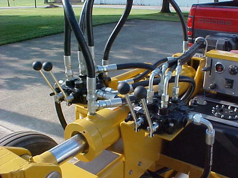
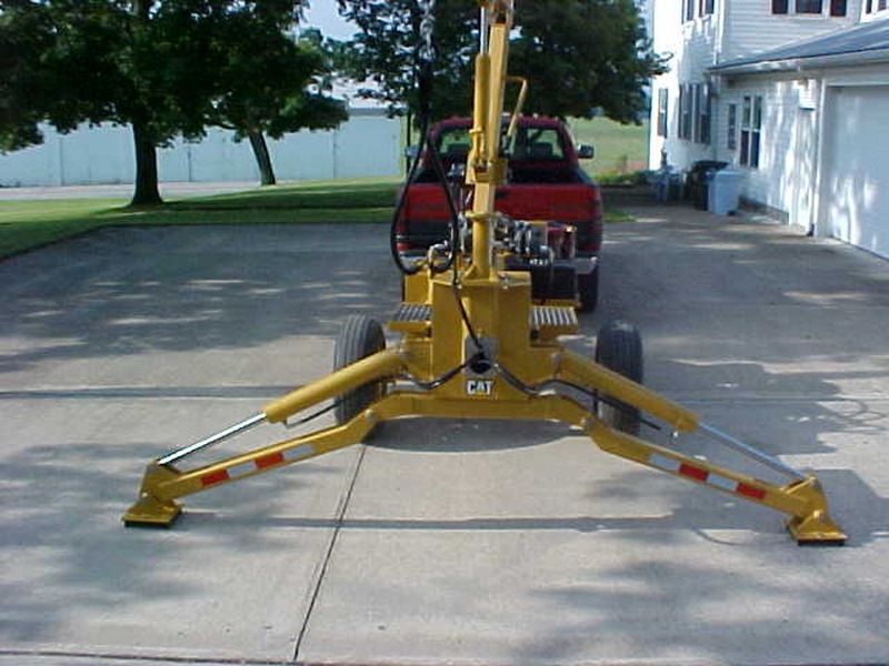
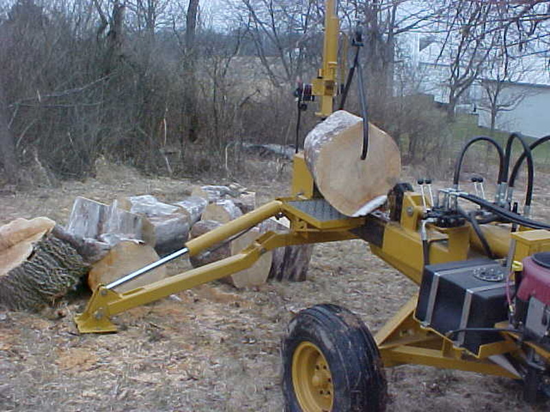
I'm happy with my "backyard stuff" splitter and I think it is just a little handier than a store bought.
SWI Don
ArboristSite Guru
I used the aluminum adapter for a horizontal setup from Surplus Center. When I figured it out, I could use a plate with both the bolt patterns for the vertical shaft motor and the adapter. I use flat head screws that I welded into the countersunk holes to in effect make studs to attach the motor and pump mount to each other via the plate.
It is pretty much like Kevin used above except I used a different pump mount. So +1 on Kevin
It is pretty much like Kevin used above except I used a different pump mount. So +1 on Kevin
Wood Hound
ArboristSite Operative
Hey Kevin,your stuff,is not Backyard stuff...
Hey Kevin,your stuff,is not Backyard stuff...
Not store bought either. Sometimes you have to make your own stuff to fit your needs and wishes.
Wood Hound
ArboristSite Operative
I did follow your BUILD, and it is outstanding,to say the least..
I did follow your BUILD, and it is outstanding,to say the least..
By the way, we never did hear anymore from the guy with the Eastonmade splitter issues. Shocking!
Wood Hound
ArboristSite Operative
Sold my 22-28 hint
milkie62
ArboristSite Guru

After drilling the holes I recessed the adapter plate holes on the motor side. Normal bolts would hit the bottom of the motor and needed a way to hold them. I used angle head allens and TIG welded them into the countersunk holes

Tack weld and check everything and weld it solid.


I'm happy with my "backyard stuff" splitter and I think it is just a little handier than a store bought.
There is always a smart aleck on here who tries to think they are the best. Well sir,Kevin YOU ARE THE BEST.Can I be your neighbor ? High HP vertical shafts are cheap compared to horiz shaft engines. You make it look simple. Thanks I will save these pics.
Belt drive
I have made many a pattern like Kevin's example. It works well. I few years back I bought a drill press with a round table that turns. Since then when I need to drill a bolt circle I chuck up a scribe in the drill and mark the center of my circle. I then swing the drill table to the side half the dia of the circle and lock the table down. I just lower the chuck down until the scribe hits the plate metal and spin the table. This give me a perfect bolt circle. If you use a thick plate, you can drill and tap the holes for your pump mount. This way you don't need to weld studs to the plate. The scribe provides a location for your center punch and you can remove the scribe from the chuck and install your drill bit and have your bolt holes align perfectly. I tend to get a little off with my drilling using the cardboard templet. At any rate, mark you engine mount and your pump mount before unclamping the metal from your drill table and the pump and engine should line up without any shimming or guess work and no welding that can warp your mount.
Similar threads
- Replies
- 3
- Views
- 513
- Replies
- 7
- Views
- 457
- Replies
- 27
- Views
- 3K


